MT-HV
| Name |
|---|---|
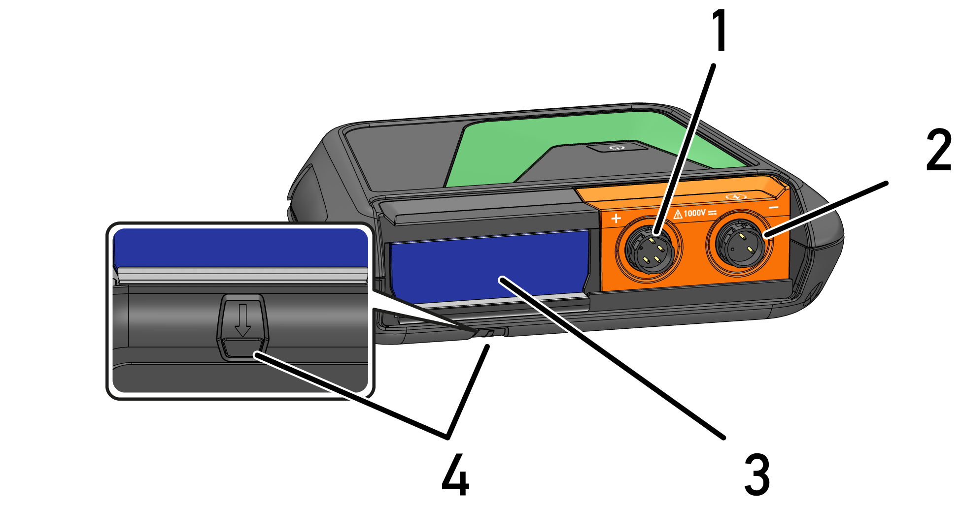
1 | Connecting the high-voltage test leads Connect the red high-voltage test lead. |
2 | Connecting the high-voltage test leads Connect the black high-voltage test lead. |
3 | Module slot Insert another module (e.g. MT 77) into the module slot. |
4 | Unlocking button
|
| Name |
|---|---|
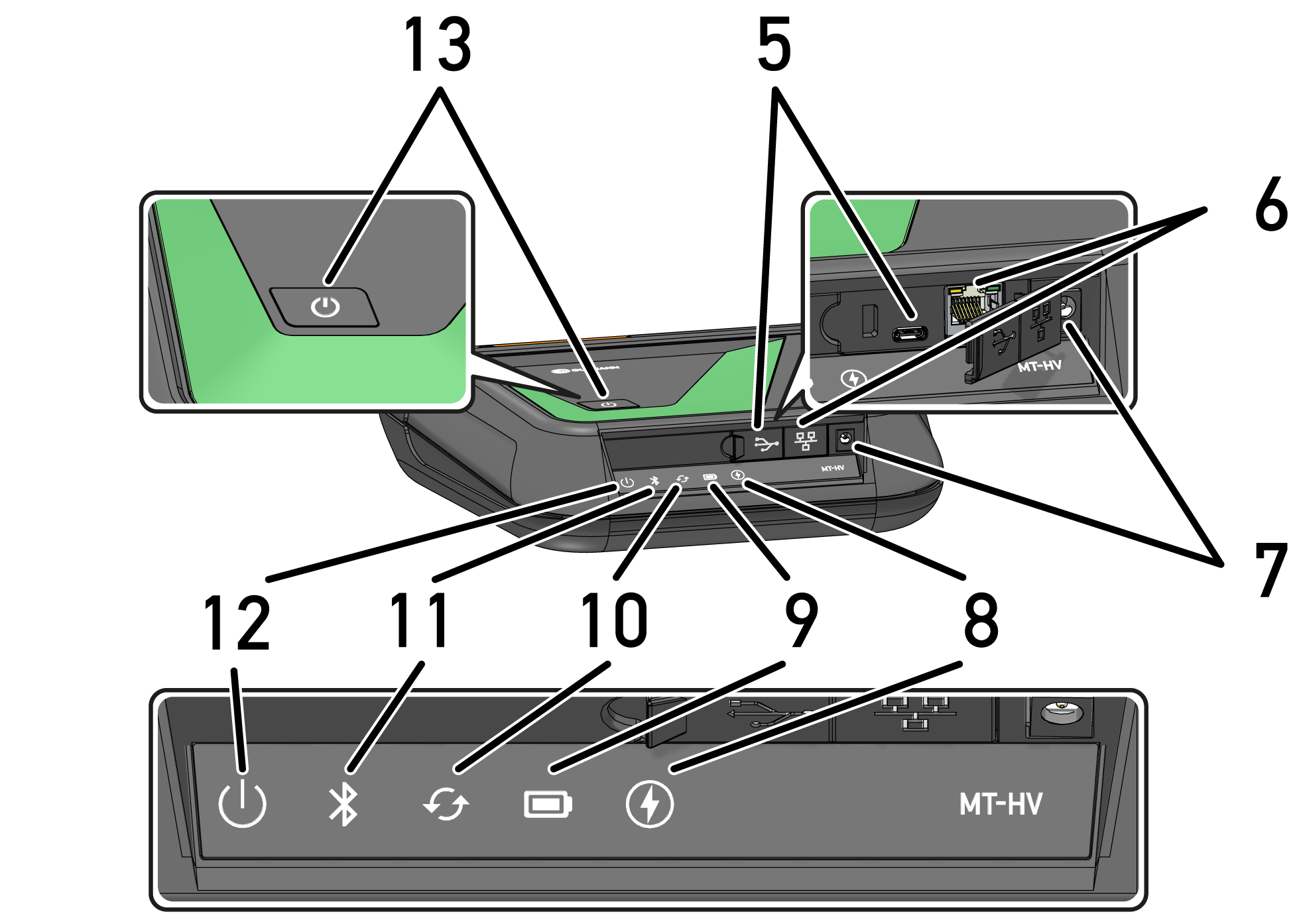
5 | USB-C interface |
6 | Ethernet interface |
7 | Power supply socket Connect a power adapter to the power supply socket to supply the MT-HV with voltage and to charge the internal battery. |
8 | High-voltage This LED indicates if e.g. a high-voltage measurement process is active or if high voltage is applied to the test prods (e.g. in case of insulation resistance measurement). The different status indications are explained in the section User Communication. |
9 | Battery status display This LED indicates the various battery charging states. The different battery status display are explained in the section User Communication. |
10 | Update This LED indicates that an update is in progress. |
11 | Bluetooth® This LED indicates that the MT-HV is connected via Bluetooth®. |
12 | MT-HV status This LED indicates e.g. if the MT-HV is active or ready for operation. The different status indications are explained in the section User Communication. |
13 | ON/OFF button Switch the MT-HV on and off with the ON/OFF button. |
| Name |
|---|---|
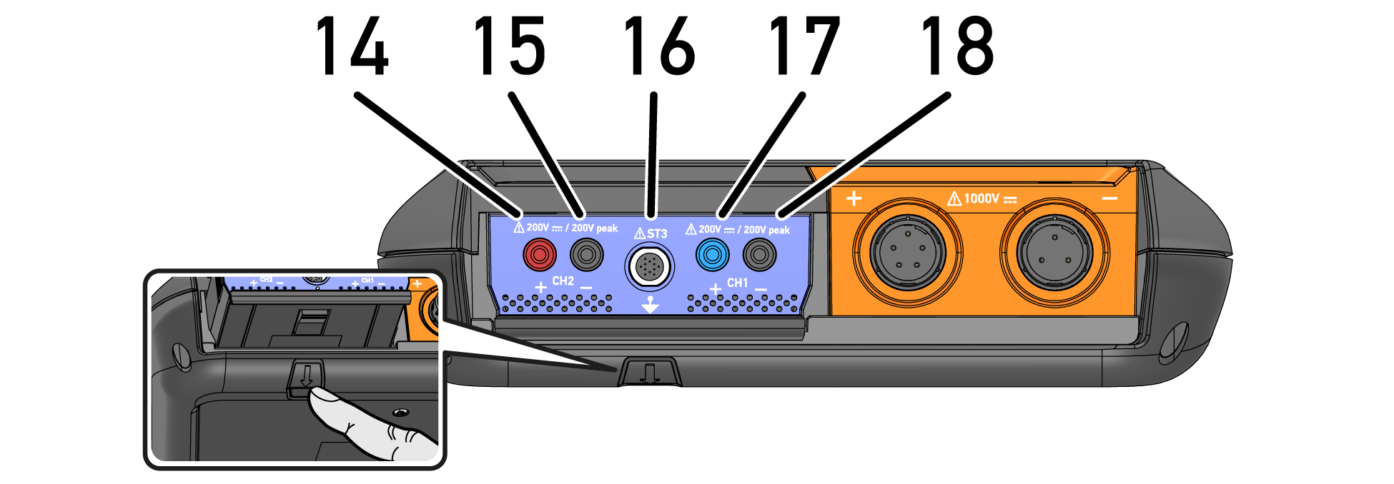
14 / 15 | Ports Scope 2 (CH2) Connect the test leads to Scope 2 (CH2) here.
|
16 | ST3 connector Connect the blue and the green clamp meter here. |
17 / 18 | Ports Scope 1 (CH1) Connect the test leads to Scope 1 (CH1) here.
|